I2DC
(Image to Design Contour)
(Image to Design Contour)
I2DC is a specialized tool for the OPC / Lithography engineer who needs to compare simulation with real silicon to analyze the OPC workflow and perform adjustments as needed.
I2DC works with a collection of overlapping high resolution images to generate a physical layout from the assembled set of images. The principal workflow proceeds as follows:
I2DC works with a collection of overlapping high resolution images to generate a physical layout from the assembled set of images. The principal workflow proceeds as follows:
- Specify a set of images that have some overlap.
- I2DC will stitch the images into a single panoramic image.
- Micron markers and textual annotations that happen to be present on the image can be removed.
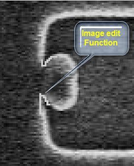
- Some input images contain artifacts that need to be ‘touched up’ prior to contour extraction. I2DC provides a set of built-in functions for image editing.
- Image processing algorithms are subsequently applied to extract contours while differentiating between current and previous layers on the image. The software supports differentiation of mixed data into separate layers.
- The rough and jagged contours are then converted to physical layout format, which means straight lines, 90-degree corners, and various allowed angles (45°, 135°, 30°, 60°, 120°, 150°).
- An optional unification step looks for duplicate shapes and builds a hierarchical layout instead of a strictly flat one.
Click for Larger
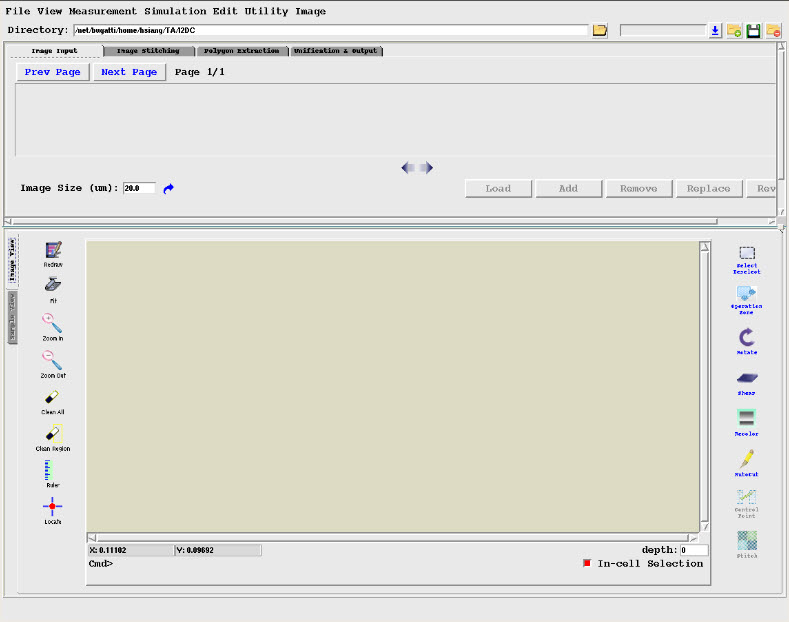
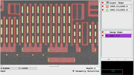
GUI Based
I2DC provides an easy-to-use GUI.

Click for Larger
Image Stitching
The first step is to assemble a panoramic image from a collection of slightly overlapping individual images.
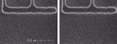
Click to Compare
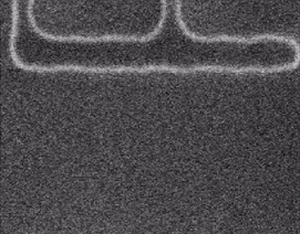
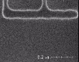
Annotation Removal
Micron markers and textual annotations can be removed.
Click for Larger
Image Editing
Some SEM or other high resolution images may need to be ‘touched up’ prior to contour extraction. I2DC provides a set of image editing functions to ensure that a better end result is produced.
Click for Larger
Layer Separation
If current and previous layer shapes in an image have sufficient grayscale difference, they can be extracted into separate layers to maintain their distinction. The result of one such conversion is shown here with two colors representing the two layers.

Click for Larger
Image to Contour to Layout Conversion
The assembled panoramic image undergoes contour extraction followed by a conversion to physical layout with the adoption of straight lines, 90-degree corners, and a set of allowed angles.

Technical Requirements
The minimum system requirements are listed below:
- Linux 2.6 or later, 64-bit, x86 based processor.
- 16 or more physical cores.
- 128 GB or more physical memory.
- 2 TB or more available hard drive capacity.